IEC ALARMS UPGRADE KIT WITH CONTROL BOARD


Replaces Datex-Ohmeda 2090844-001IEC ALARMS UPGRADE KIT WITH CONTROL BOARD
 Exchange
Goods sold on an "Exchange" basis require that Buyer return a like, repairable item within 15 days (or the seller's specified time frame) in order to receive the price quoted. For full details, see Terms and Conditions.

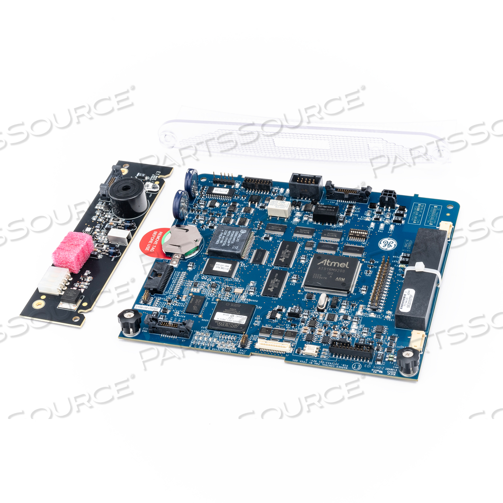
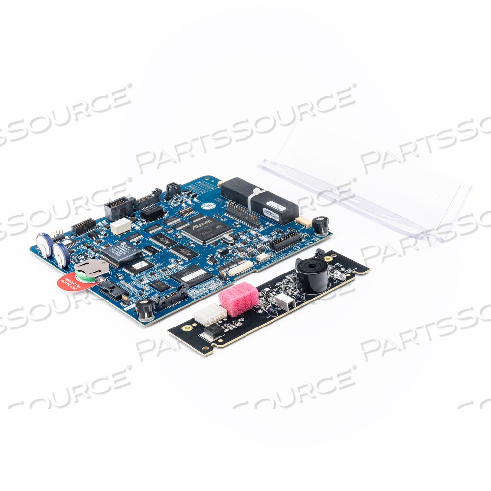
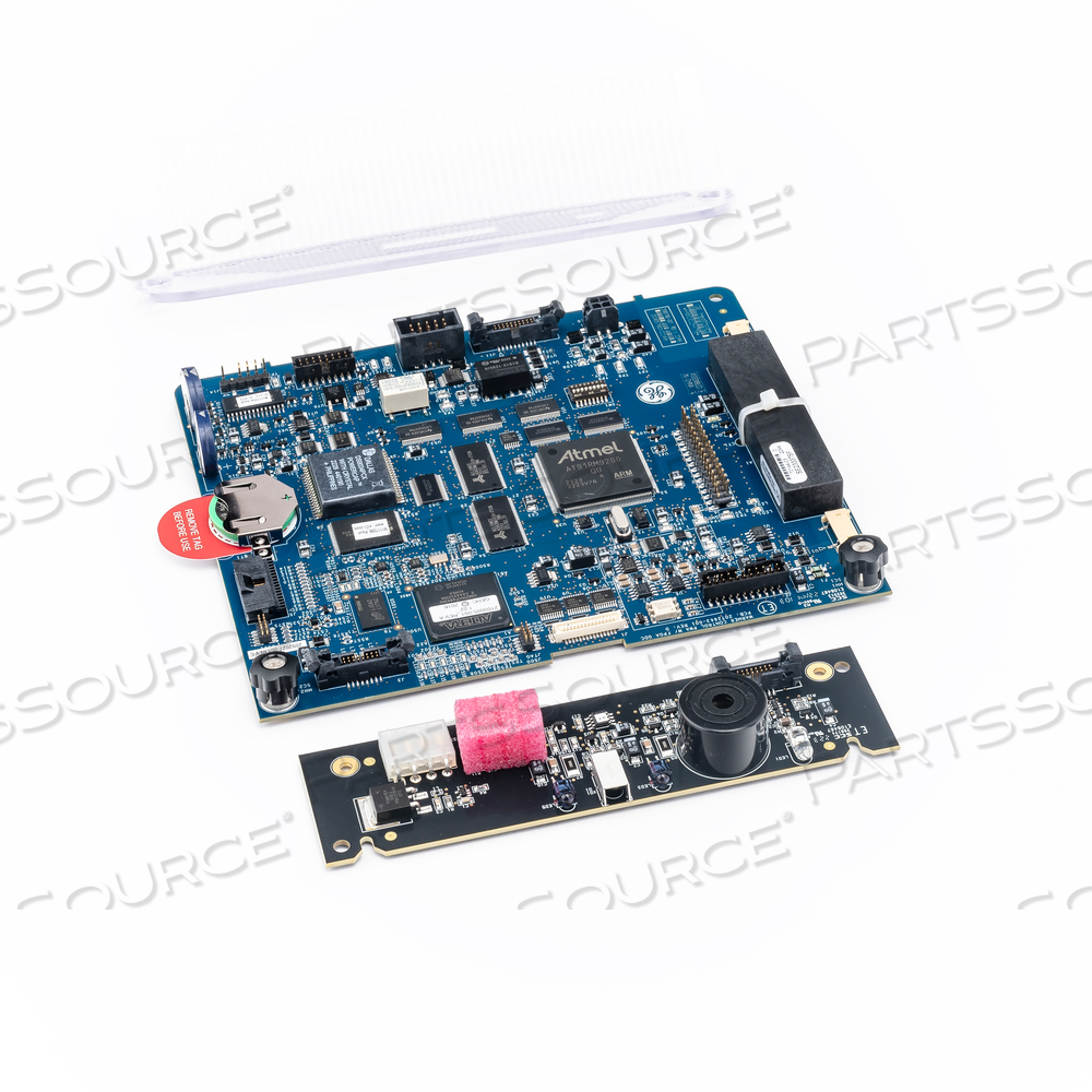
The IEC Alarms Upgrade Kit with Control Board consist of alarm lens, warmer alarm light PCA with white LED, warmer control board with FPGA GDC, label and Giraffe™ Warmer IEC alarm upgrade information manual. The alarm light board and lens are mounted on the warmer top of the electronics enclosure assembly using two captive screws. This Printed Circuit Assembly (PCA) is comprised of components including the alarm light raw PCB, resistor, capacitor, IC's, alarm buzzer, white LED, DIO-LED, Schottky diode, EMI-filter, transistor and board mounted connectors. The control board is also mounted on the warmer front of the electronics enclosure assembly using screws. This board is comprised of components including PCB, resistor, capacitor, fuse, IC's, DIO-LED, Schottky diode, EMI-filter, transistor, audio processor, main application processor, board mounted connectors, relay, power regulator, battery, crystals, connector header and programmed IC device. The alarms are indicated visually and audibly to the operator of the Giraffe™ and Panda™ Warmer products. When an alarm is triggered, alarm messages appear in the control panel, the indicator light at the top of the control panel housing is illuminated and audio tones sound. The alarms may be activated differently depending on the current operating mode. The visual alarms are provided via the LED array located on the alarm light board. The LED array is controlled on and off by the alarm control signal provided by the main application processor or audio processor on the control board. The audio alarm is generated by an audio amplifier also under control of the audio processor in response to a command from the main application processor.
 ISO 9001 Quality Management
 ISO 13485 Medical Devices
The IEC Alarms Upgrade Kit with Control Board consist of alarm lens, warmer alarm light PCA with white LED, warmer control board with FPGA GDC, label and Giraffe™ Warmer IEC alarm upgrade information manual. The alarm light board and lens are mounted on the warmer top of the electronics enclosure assembly using two captive screws. This Printed Circuit Assembly (PCA) is comprised of components including the alarm light raw PCB, resistor, capacitor, IC's, alarm buzzer, white LED, DIO-LED, Schottky diode, EMI-filter, transistor and board mounted connectors. The control board is also mounted on the warmer front of the electronics enclosure assembly using screws. This board is comprised of components including PCB, resistor, capacitor, fuse, IC's, DIO-LED, Schottky diode, EMI-filter, transistor, audio processor, main application processor, board mounted connectors, relay, power regulator, battery, crystals, connector header and programmed IC device. The alarms are indicated visually and audibly to the operator of the Giraffe™ and Panda™ Warmer products. When an alarm is triggered, alarm messages appear in the control panel, the indicator light at the top of the control panel housing is illuminated and audio tones sound. The alarms may be activated differently depending on the current operating mode. The visual alarms are provided via the LED array located on the alarm light board. The LED array is controlled on and off by the alarm control signal provided by the main application processor or audio processor on the control board. The audio alarm is generated by an audio amplifier also under control of the audio processor in response to a command from the main application processor.
- Datex-Ohmeda
- GIRAFFE
- PANDA
- PANDA IRES
The IEC Alarms Upgrade Kit with Control Board consist of alarm lens, warmer alarm light PCA with white LED, warmer control board with FPGA GDC, label and Giraffe™ Warmer IEC alarm upgrade information manual. The alarm light board and lens are mounted on the warmer top of the electronics enclosure assembly using two captive screws. This Printed Circuit Assembly (PCA) is comprised of components including the alarm light raw PCB, resistor, capacitor, IC's, alarm buzzer, white LED, DIO-LED, Schottky diode, EMI-filter, transistor and board mounted connectors. The control board is also mounted on the warmer front of the electronics enclosure assembly using screws. This board is comprised of components including PCB, resistor, capacitor, fuse, IC's, DIO-LED, Schottky diode, EMI-filter, transistor, audio processor, main application processor, board mounted connectors, relay, power regulator, battery, crystals, connector header and programmed IC device. The alarms are indicated visually and audibly to the operator of the Giraffe™ and Panda™ Warmer products. When an alarm is triggered, alarm messages appear in the control panel, the indicator light at the top of the control panel housing is illuminated and audio tones sound. The alarms may be activated differently depending on the current operating mode. The visual alarms are provided via the LED array located on the alarm light board. The LED array is controlled on and off by the alarm control signal provided by the main application processor or audio processor on the control board. The audio alarm is generated by an audio amplifier also under control of the audio processor in response to a command from the main application processor.
 ISO 9001 Quality Management
 ISO 13485 Medical Devices
The IEC Alarms Upgrade Kit with Control Board consist of alarm lens, warmer alarm light PCA with white LED, warmer control board with FPGA GDC, label and Giraffe™ Warmer IEC alarm upgrade information manual. The alarm light board and lens are mounted on the warmer top of the electronics enclosure assembly using two captive screws. This Printed Circuit Assembly (PCA) is comprised of components including the alarm light raw PCB, resistor, capacitor, IC's, alarm buzzer, white LED, DIO-LED, Schottky diode, EMI-filter, transistor and board mounted connectors. The control board is also mounted on the warmer front of the electronics enclosure assembly using screws. This board is comprised of components including PCB, resistor, capacitor, fuse, IC's, DIO-LED, Schottky diode, EMI-filter, transistor, audio processor, main application processor, board mounted connectors, relay, power regulator, battery, crystals, connector header and programmed IC device. The alarms are indicated visually and audibly to the operator of the Giraffe™ and Panda™ Warmer products. When an alarm is triggered, alarm messages appear in the control panel, the indicator light at the top of the control panel housing is illuminated and audio tones sound. The alarms may be activated differently depending on the current operating mode. The visual alarms are provided via the LED array located on the alarm light board. The LED array is controlled on and off by the alarm control signal provided by the main application processor or audio processor on the control board. The audio alarm is generated by an audio amplifier also under control of the audio processor in response to a command from the main application processor.
- Datex-Ohmeda
- GIRAFFE
- PANDA
- PANDA IRES
The IEC Alarms Upgrade Kit with Control Board consist of alarm lens, warmer alarm light PCA with white LED, warmer control board with FPGA GDC, label and Giraffe™ Warmer IEC alarm upgrade information manual. The alarm light board and lens are mounted on the warmer top of the electronics enclosure assembly using two captive screws. This Printed Circuit Assembly (PCA) is comprised of components including the alarm light raw PCB, resistor, capacitor, IC's, alarm buzzer, white LED, DIO-LED, Schottky diode, EMI-filter, transistor and board mounted connectors. The control board is also mounted on the warmer front of the electronics enclosure assembly using screws. This board is comprised of components including PCB, resistor, capacitor, fuse, IC's, DIO-LED, Schottky diode, EMI-filter, transistor, audio processor, main application processor, board mounted connectors, relay, power regulator, battery, crystals, connector header and programmed IC device. The alarms are indicated visually and audibly to the operator of the Giraffe™ and Panda™ Warmer products. When an alarm is triggered, alarm messages appear in the control panel, the indicator light at the top of the control panel housing is illuminated and audio tones sound. The alarms may be activated differently depending on the current operating mode. The visual alarms are provided via the LED array located on the alarm light board. The LED array is controlled on and off by the alarm control signal provided by the main application processor or audio processor on the control board. The audio alarm is generated by an audio amplifier also under control of the audio processor in response to a command from the main application processor.
 ISO 9001 Quality Management
 ISO 13485 Medical Devices
The IEC Alarms Upgrade Kit with Control Board consist of alarm lens, warmer alarm light PCA with white LED, warmer control board with FPGA GDC, label and Giraffe™ Warmer IEC alarm upgrade information manual. The alarm light board and lens are mounted on the warmer top of the electronics enclosure assembly using two captive screws. This Printed Circuit Assembly (PCA) is comprised of components including the alarm light raw PCB, resistor, capacitor, IC's, alarm buzzer, white LED, DIO-LED, Schottky diode, EMI-filter, transistor and board mounted connectors. The control board is also mounted on the warmer front of the electronics enclosure assembly using screws. This board is comprised of components including PCB, resistor, capacitor, fuse, IC's, DIO-LED, Schottky diode, EMI-filter, transistor, audio processor, main application processor, board mounted connectors, relay, power regulator, battery, crystals, connector header and programmed IC device. The alarms are indicated visually and audibly to the operator of the Giraffe™ and Panda™ Warmer products. When an alarm is triggered, alarm messages appear in the control panel, the indicator light at the top of the control panel housing is illuminated and audio tones sound. The alarms may be activated differently depending on the current operating mode. The visual alarms are provided via the LED array located on the alarm light board. The LED array is controlled on and off by the alarm control signal provided by the main application processor or audio processor on the control board. The audio alarm is generated by an audio amplifier also under control of the audio processor in response to a command from the main application processor.
- Datex-Ohmeda
- GIRAFFE
- PANDA
- PANDA IRES

 Exchange